AOS-3568H
Product introduction:
功能&接口 Function & Interface | 详细描述 Detailed Description |
CPU | RK3568 Cortex-A55四核,最高主频2.0GHz RK3568 Cortex-A55 quad-core, up to 2.0GHz |
DDR | LPDDR4 2GB(4GB|8GB可选) LPDDR4 2GB (4GB|8GB optional) |
存储 Storage | 默认标配8GB EMMC NAND芯片,可扩展至最大128GB The default comes with an 8GB EMMC NAND chip that can scale up to 128GB |
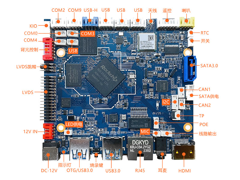
LVDS | 30针行业标准双路LVDS接口,支持VESA/JEITA格式,最高支持1080P输出 30-pin industry-standard dual LVDS supporting VESA/JEITA format up to 1080P output |
HDMI输出 HDMI Output | HDMI 2.0a标准显示接口,最高支持4K输出 HDMI 2.0a standard display interface supports up to 4K output |
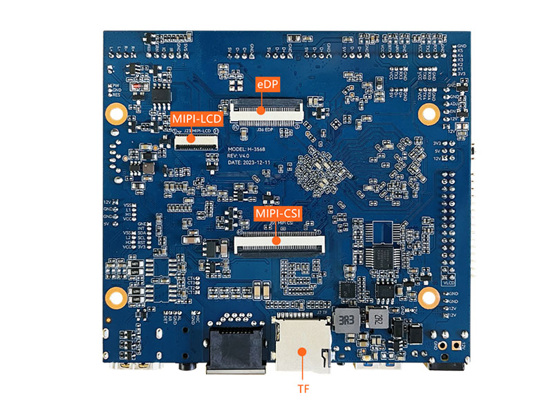
MPI-DSI输出 MIPI-DSI Output | 31针行业标准FPC MIPI屏接口,可扩展MIPI显示输出 31-Pin common MIPI DSI interface for extended MIPI panel sub-board |
EDP | 30针行业标准FPC EDP接口,支持1~2通道模式,最高支持1080P输出 30-pin common FPC EDP supporting 1~2 lanes format up to 1080P output |
MIPI-CSI | 40-Pin FPC 双目MIPI-CSI摄像头接口 40-Pin FPC Dual MIPI-CSI camera port |
耳机/麦克 HP/MIC | 支持美标4段耳麦一体3.5mm插座(左-右-地-麦克) Support CTIA 4-pole HP/MIC socket (Left-Right-GND-Mic) |
线路输出 Line Output | 支持标准左右声道线路输出(排针接口) Support standard left and right channel line output (pin header) |
功放输出 Amplifier output | 8欧・6W双路音频功放输出 8 Ohm 6W Dual Audio Amplifier Output |
MIC输入 MIC Input | 单独MIC输入(排针接口) Single-End MIC input (pin header) |
USB接口 USB Interface | 2个外置横插USB 3.0接口(单层插座,其中一个为OTG口),5个内置排针(其中一个CPU直通USB) 2 horizontal USB 3.0 connectors (Single Socket,one is for OTG), 5 pin headers (one is CPU raw USB) |
串口 Serial Port | 4个TTL/RS-232兼容内置、1个TTL/RS-485兼容内置 4 TTL/RS-232 compatible, 1 TTL/RS-485 compatible |
TF卡 Micro SD Card | 自弹式TF卡插座,最高支持256GB TF卡 Self-elastic micro SD card socket, up to 256GB capacity |
摄像头 Camera | 支持800万像素以内USB摄像头 Support USB camera within 8 million pixels |
WiFi | 内置高性能SDIO接口WiFi6模块,支持IEEE 802.11 b/g/n/ax,默认单频2.4GHz WiFi Built-in high performance SDIO interface WiFi6 module, support IEEE 802.11 b/g/n/ax |
蓝牙 Bluetooth | 内置高性能串口BT模块,支持V2.1+EDR/BT v3.0/ BT 4.x/BT v5.2 Built-in high performance serial interface BT module (optional) with support for V2.1+EDR/BT v3.0/BT v4.x/BT v5.2 |
以太网口 Ethernet | 10/100/1000M自适应以太网RJ45网口 10/100/1000M Adaptive Ethernet RJ45 connector |
背光控制 Backlight Control | 行业标准液晶屏背光控制接口,支持背光开关和亮度调节 Industry standard LCD backlight control header, support for backlight switch and brightness adjustment |
红外遥控 Infrared RC | 标准红外接收排针接口 Standard infrared receiver pin header |
GPIO信号 GPIO Signals | 5路GPIO信号,可扩展GPIO按键和/或3.3V输入/输出 5-way GPIO signals for such as GPIO buttons and/or 3.3V digital input/output |
I2C总线 I2C Bus | I2C排针+FPC接口,可扩展I2C电容屏等 I2C pin header and FPC for I2C capacitive screen and etc |
CAN总线 CAN Bus | 2路CAN排针接口,可扩展CAN总线外设 2 CAN pin header for CAN Bus peripherals |
SATA硬盘 SATA HD | 标准SATA 3.0硬盘接口(带电源排针) Standard SATA 3.0 hard disk port with power supply header |
实时时钟 Real Time Clock | 超低功耗RTC电路(带CR1220纽扣电池),并可支持定时开关机 Ultra-low-power RTC circuit (CR1220 battery) with timer and alarm functionalities |
指示灯 LED Indicator | 蓝色工作指示灯 Blue LED indicator for running |
按键 Buttons | 烧录键(RECOVERY)和电源键 Recovery mode button and power switch button |
电源输入 DC Input | 支持9~15V宽电压直流电源输入 Supports 9~15V wide voltage DC power input |
环境要求 Ambient Requirement | 工作温度-20°C ~ 70°C,工作湿度0%~95%(不结露) Working temperature -20°C ~ 70°C, working humidity 0% ~ 95% (non-condensing) |
物理尺寸 Physical Size | 长*宽*高(100mm*90mm*9mm),PCB正面高度7mm Length*Width*Height (100mm*90mm*9mm), PCB top side height 7mm |
操作系统 Operating Version | 推荐安卓11,可选Linux Buildroot/Debian 10/Ubuntu-20.04和鸿蒙OpenHarmony 3.2 Recommended Android 11,Linux Buildroot/Debian 10/Ubuntu-20.04 and OpenHarmony 3.2 optional |